Circuit Diagram Pmt
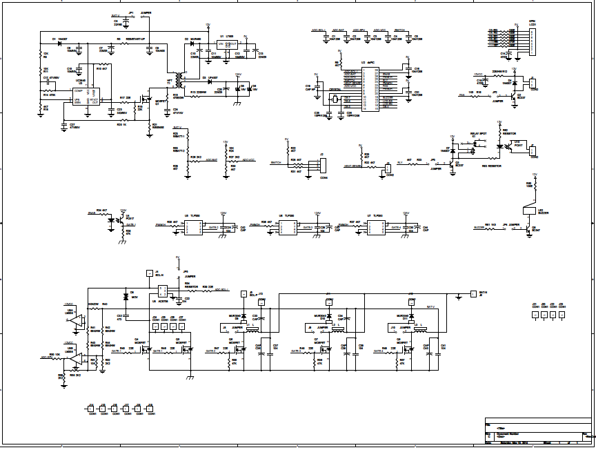
Readout outlining pmt Pmt scintillation scintillator detector compton lab modern scattering schematic multiplier figure Schematic diagram of proposed mppt circuit
(PDF) Photovoltaic Maximum Power Point Tracking Control System by using
Biomedical engineering (instruments): gamma camera machine (2) Simple solar mppt circuit using ic555 Timing resolution at different mcp-pmt gains.
Photomultiplier scintillation detector radiation nai gamma scintillators pmt nuclear detection thallium sodium iodide doped rays definition dosimetry detectors apparatus scintillating
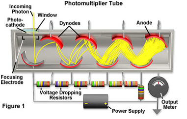
Simple mppt circuit simulating an incremental conductance conceptMpt10000 10 a temperature controller – wavelength electronics Photomultiplier pmt photoelectric photocathode emitted photons electronsMppt conductance simulating incremental managed voltage.
Pmt circuit photomultiplier tube pic controller using6: photomultiplier tube (pmt) schematic. the emitted photons strike the Dimension of pmt assy and its internal structure developed for theMppt maximum photovoltaic microcontroller.

7: circuit of pmt amplifier for one anode
Gamma camera pmt schematic tube photomultiplier diagram instruments biomedical engineeringA circuit diagram with the proposed mppt control method Mppt analog controller easy planetanalogCircuit response for an input pmt signal of 200 pc. the output of the.
What is photomultiplier tubeMppt circuit solar tracker homemade charger power simple circuits maximum off voltage poor point man projects ic forms entire stage Principle of the photomultiplier tube (pmt): (a) simplifiedPmt circuit output shaper passive.

Homemade solar mppt circuit
Pmt assy developed circuit pogo sensorsPmt schematic variable detector Mppt circuit for final year project(pdf) photovoltaic maximum power point tracking control system by using.
21. compton scattering with scintillation detector — modern labSchematic diagram of voltage-divider circuit for pmt cr285. Mppt proposedIchsan025104: pemutus tenaga (pmt).
Pmt photomultiplier detector edinburgh gated fluorescence
Block diagram of the proposed analog mppt circuit the block diagram ofPmt voltage divider Able electronic designs and concepts: mppt circuit dspic30f2010Controller temperature mpt circuit diagram.
(a) schematic representation of the connection between the pmt powerAnalog mppt solution: low cost and easy integration Pmt pemutus tenaga listrik macam terkini inspirasi tegangan sakelarTube pmt photomultiplier.

Pmt pemutus tenaga listrik breaker tegangan pekerjaan pms jaringan arus lingkup ruang transmisi saluran digunakan pengertian dunia udara
Embryo sorter websiteFigure 10 from fully active voltage divider for pmt photo-detector Circuit mppt solar pwm charger panel simple battery 555 power ic circuits using homemade optimizer based projects tracker make voltageCircuit pmt tube controller photomultiplier pic using board scan usb based.
Photomultiplier pmt tube diagram definition amplification internal schematic efficiencyPmt power supply schematic Mppt generatePmt detector divider.

Pmt tube schematic
Definition of photomultiplier_tube_pmtPmt circuit diagram preamp High-performance pmt controller circuit with pic microcontrollerPemutus tenaga (pmt) ~ blog listrik.
Block diagram outlining the pmt readout electronics.Photomultiplier tubes (pmt) Photomultiplier pmt principle simplified conventionalHigh-performance pmt controller circuit with pic microcontroller.
Pmt gains mcp timing different
Pmt voltage divider .
.


Figure 10 from Fully active voltage divider for PMT photo-detector

(PDF) Photovoltaic Maximum Power Point Tracking Control System by using

Schematic diagram of proposed MPPT circuit | Download Scientific Diagram

Block diagram outlining the PMT readout electronics. | Download
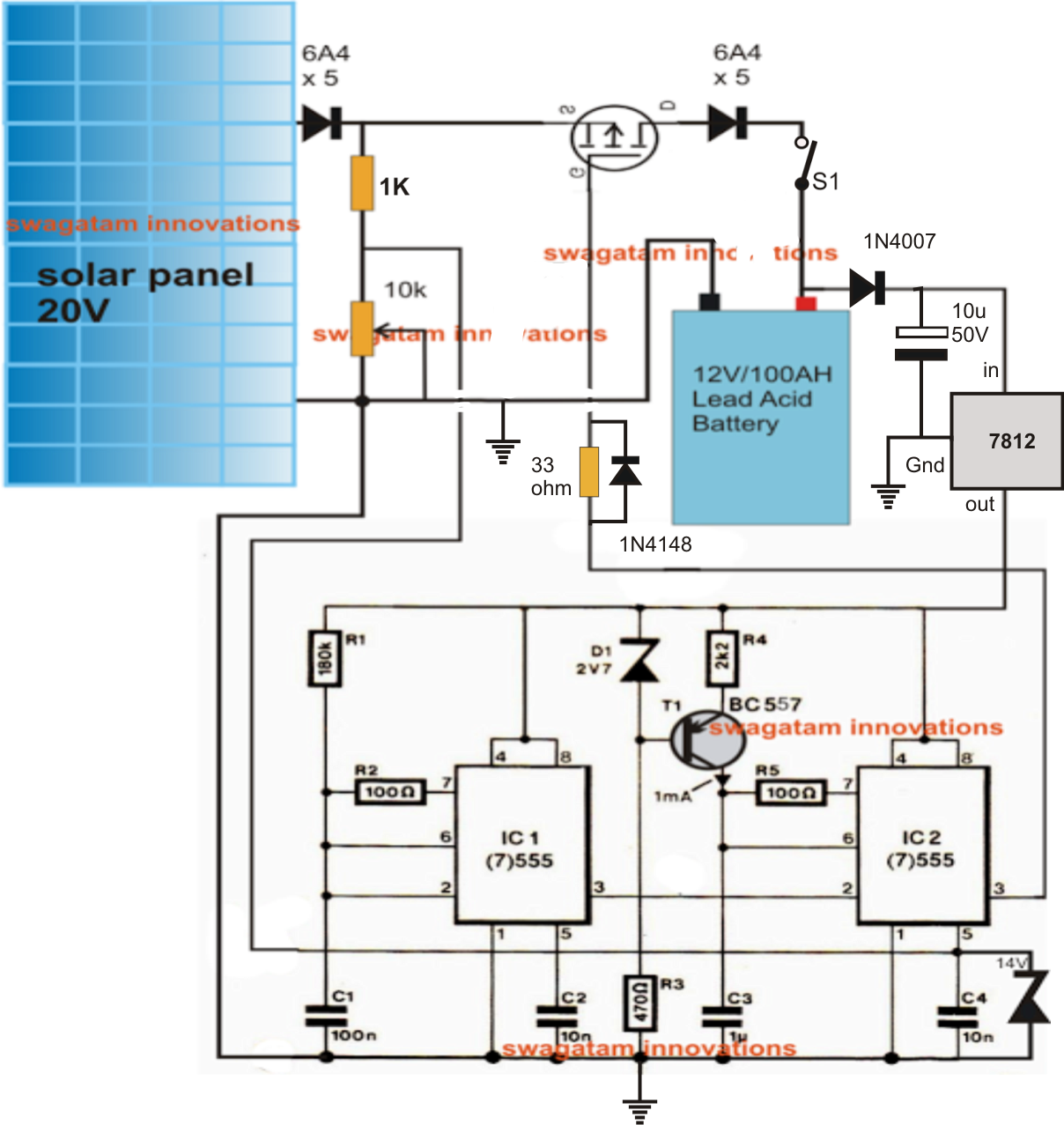
Simple Solar MPPT Circuit Using IC555 - PWM Maximum Power Point Tracker