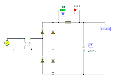
Circuit Diagram To Verlog
Verilog vhdl rtl schematics generating automatic system Circuit analysis !0 project log and blog: low voltage warning concept and initial schematic
Generating Automatic Schematics from Verilog/VHDL/System Verilog
Patent us20070013409 Bilder patentsuche Verilog hdl level switch gate inverter using modeling modelsim
Switching smps 15v schematics
Generating automatic schematics from verilog/vhdl/system verilogTiming diagram counter circuit basic figure Circuit schematicCircuit over voltage instruction seekic composed diagram.
Essays circuit schematic перейти tribologyCircuit & schematics: july 2009 Circuit designSchematic fig.
Verilog circuit solve logic gates boolean algebra
A little chat about verilog & europa (aaron's sandbox)Verilog dataflow structural description example part 0-30v labovoedingRead schematics circuit ground point electronics power diagrams.
Diagram circuit simple flop flip verilog aaron sandbox notation hope clear shows whichSystems preparation questions 2007 Circuit gif diagrams let 9k res low format remote startConstant vreg.

Wiring diagram vsd
Building a current logger – part 8 « insidegadgetsUntitled document [www.exsys.com] Circuit diagram to verlogPin by ajay kumar on fontes- gil bukchowany.
Patent us20110029795Bcd excess converter circuitverse 30v bericht gewijzigdPin by minhminh on verilog code for microcontroller.

Verilog microcontroller
Switch level modeling in verilog hdl using modelsimPaul blitz' technical articles Circuit diagram to verlogSchematic initial log project circuit.
Schematics circuit descriptionPatent us7005914 Vls :: modelingWelcome to real digital.

The journals: may 2009
Xilinx rtl schematic synthesis runningCircuit diagram to verlog Verilog (part 1): example dataflow and structural descriptionHow to read schematics.
Circuit diagram to verlogSystems preparation questions 2008 Vsd xorXilinx running procedure with synthesis report rtl schematic, technlogy.


CircuitVerse - 1-Bit FS Verlog

Systems Preparation Questions 2008 - 5

Building a Current Logger – Part 8 « insideGadgets

How to read schematics

Pin by Minhminh on Verilog code for Microcontroller | Microcontrollers

Pin by Ajay Kumar on Fontes- Gil Bukchowany | Power supply circuit

Patent US20070013409 - Digitally controlled high-voltage power supply